Posts

Electric car kit approved ?. Yes, in Spain and Europe.

In recent years, electric cars have become more and more common, and the question,often is: which electric car to buy?.

With the new European directives, regulations to reduce CO2 emissions, the inflation of raw materials (copper, aluminum, lithium, etc.) and the problems in the supply chain, it becomes increasingly obvious that the way forward is to retrofit, that is to convert a car into electric.

The most obvious advantage is the price, and that is that converting a small city vehicle with a car conversion kit to electric can have the same or less price than buying an electric car without a license.

And without looking at the price, the fact of giving our planet earth less work and making real use of the circular economy is the most important reason.

By buying an electric car, we will have promoted the manufacture of a car from scratch, with the resulting waste of energy and resources, while converting it with a conversion kit, we will be recycling and reusing a car that would otherwise go to scrap.

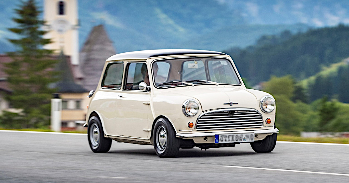
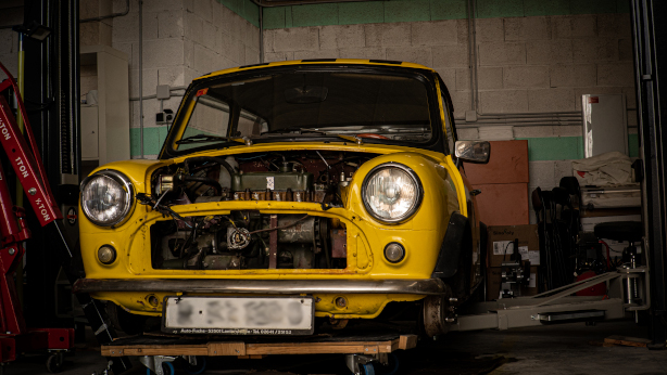
Well, we are ready to offer our first “approved car kit in Spain” (and in Europe), in this case for the fabulous classic Mini. And more approved kits will follow the Mini: VW Beetle, Seat 600, Seat Ibiza, Renault Kangoo,…

The kit will be tested, approved and ready for distribution in 2023.

And what does this approved kit consist of?

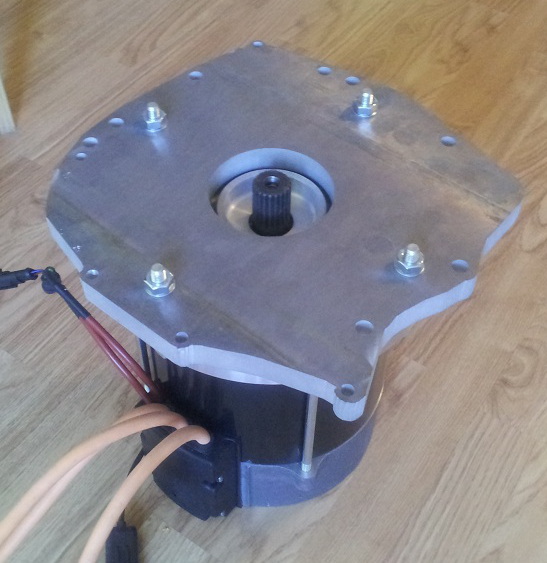
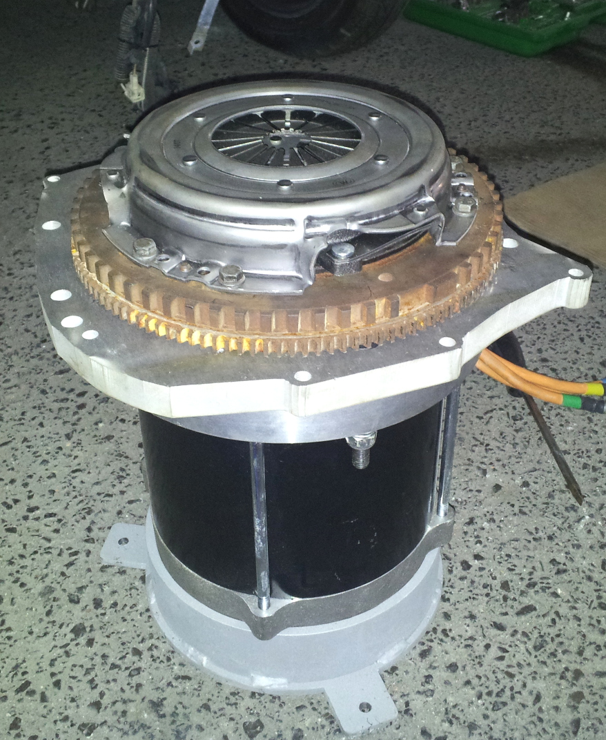
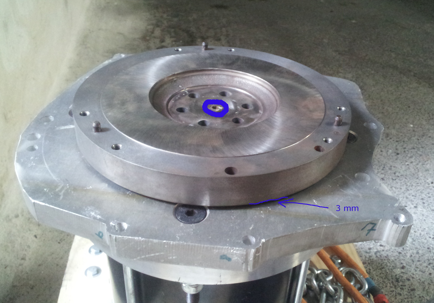
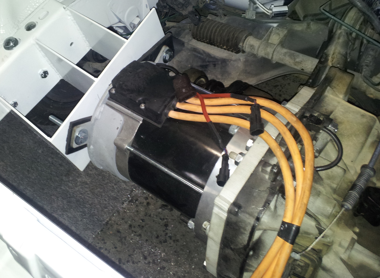
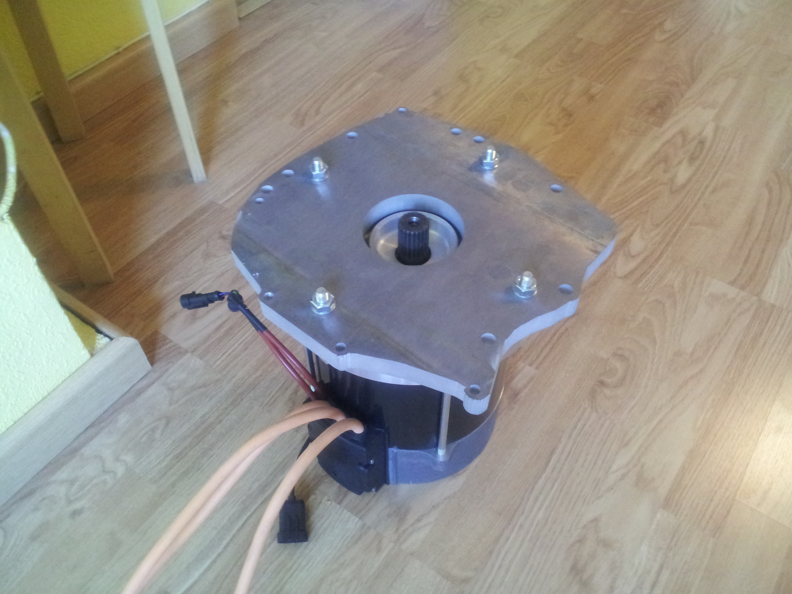
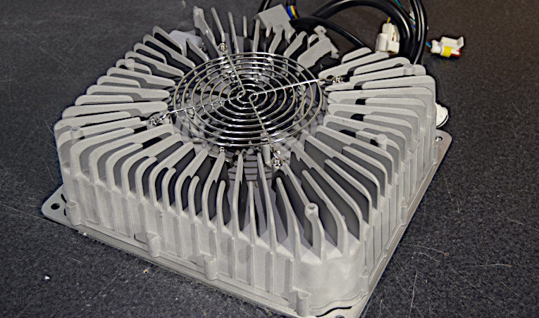
The kit has a three-phase induction electric motor of 18Kw of sustained power and 35Kw of maximum power. Air-cooled and weighing about 50Kg, it will be capable of developing a maximum torque of 150Nm.

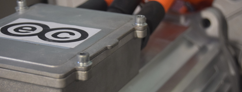
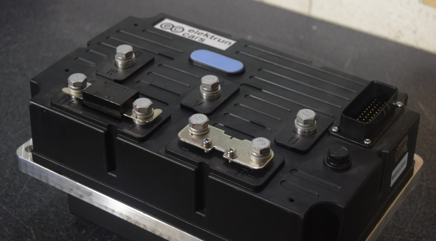
The brain of this kit will be a 108V controller with a sustained output current of about 250A, air-cooled, which makes it easier to maintain, and with a power capacity of up to 55Kw and an energy efficiency of 98%.

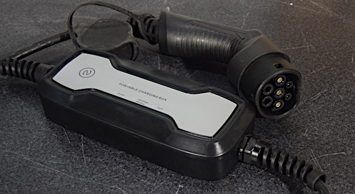
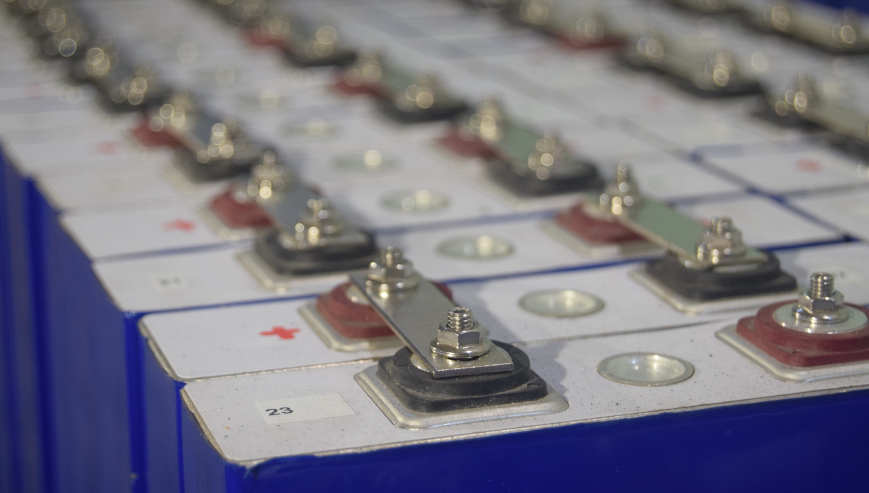
The batteries for the prototype will be a 10Kw lithium battery pack with its corresponding charger (the final battery pack is yet to be determined), more than enough for urban use for the Mini.

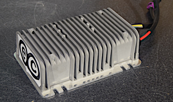
It also has a 12V dc-dc converter so that the auxiliary battery continues to power the car lights.

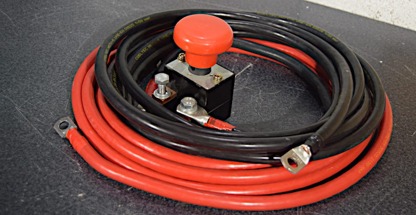
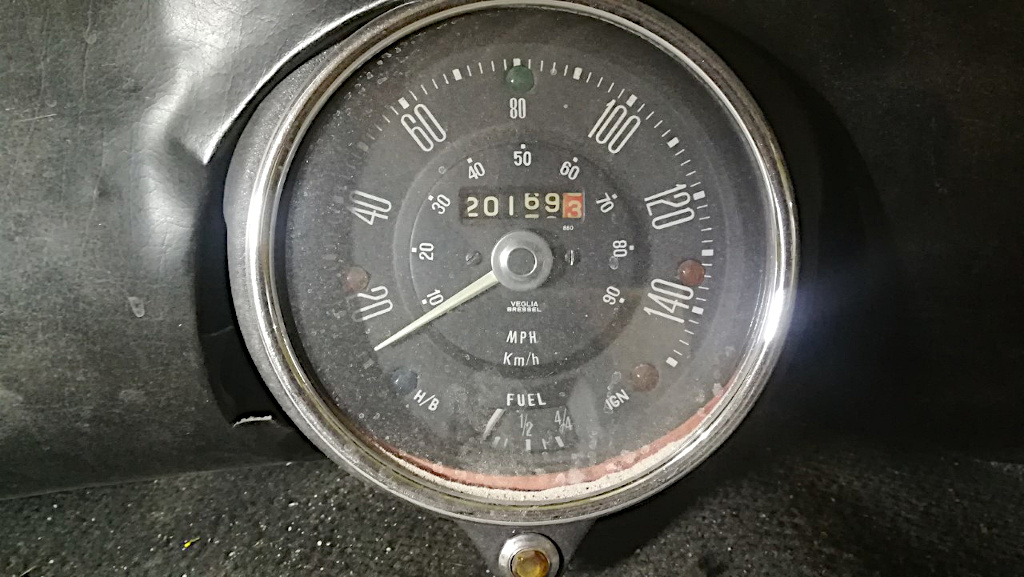
Also, the kit will have all the other extras such as signal wiring, high-voltage cable (so that the conversion is very simple without the need to add anything else) and a console with all the information on the Mini (led aesthetics or Mini aesthetics)

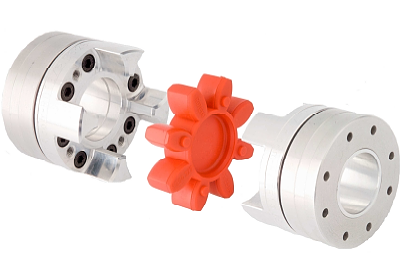
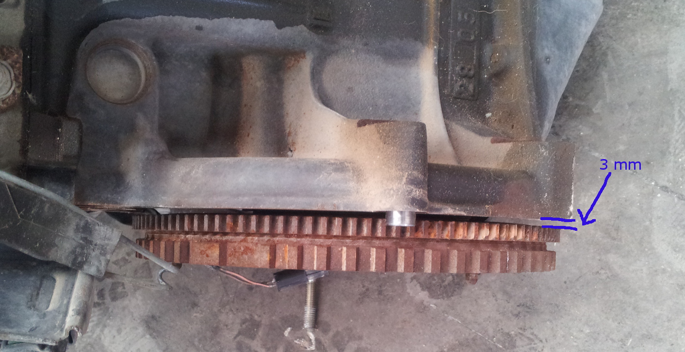
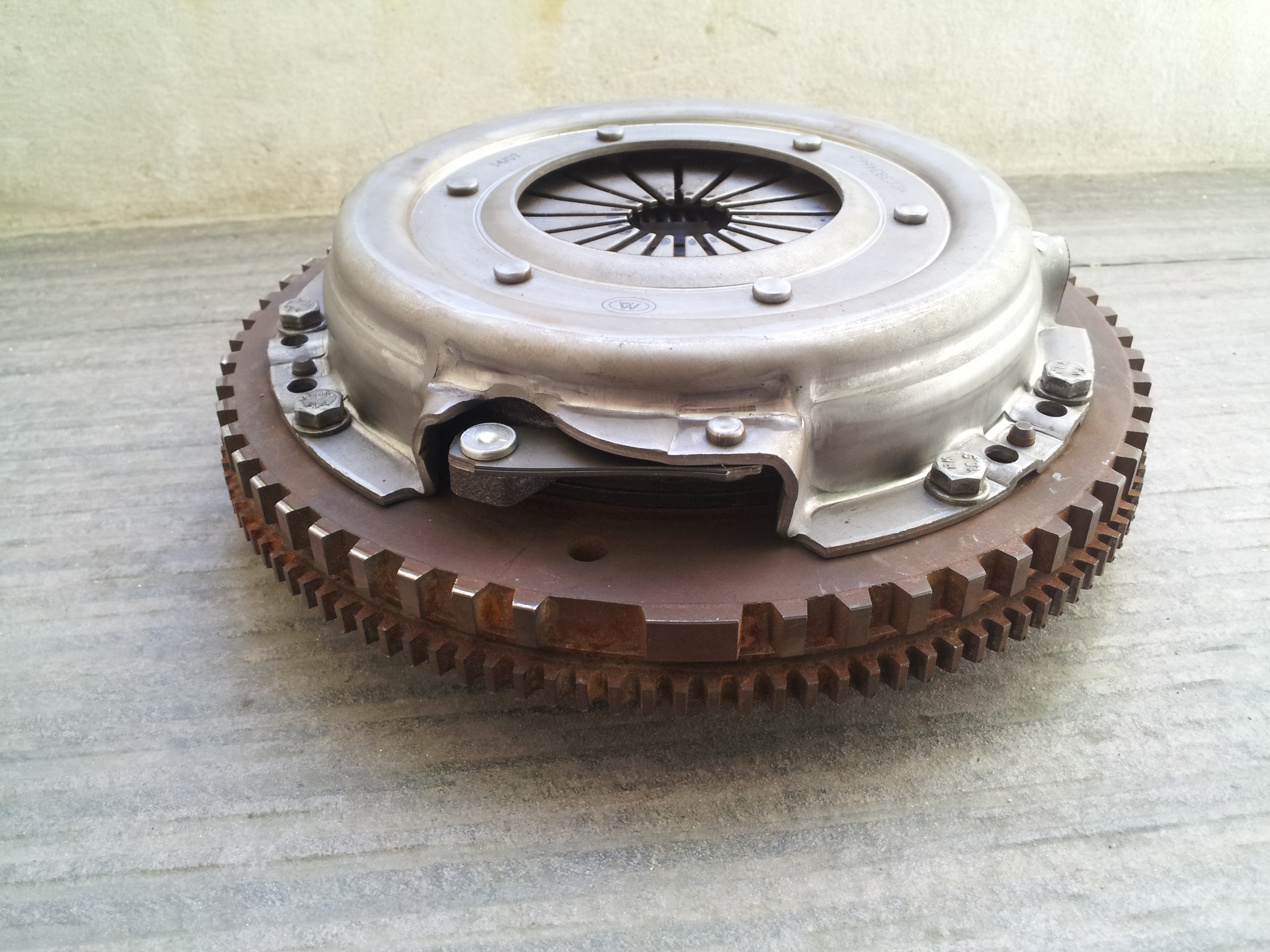
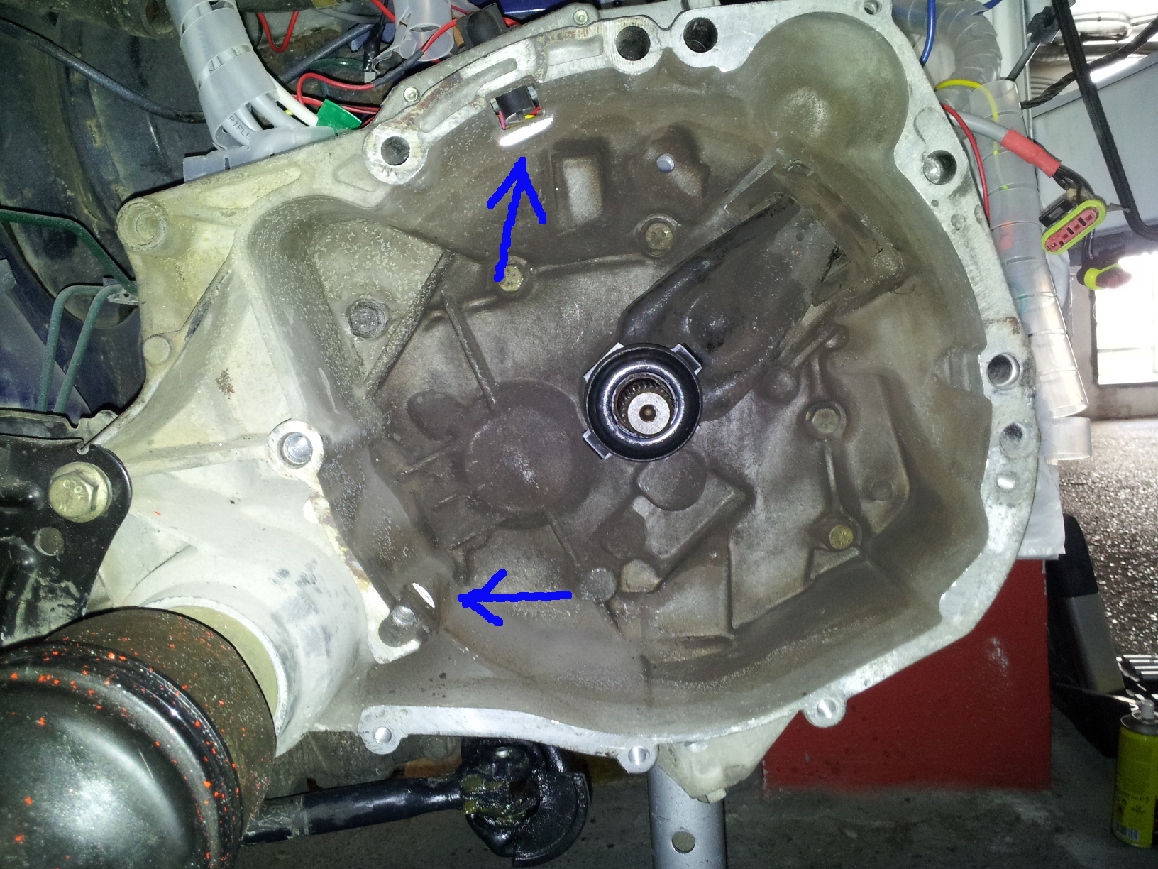
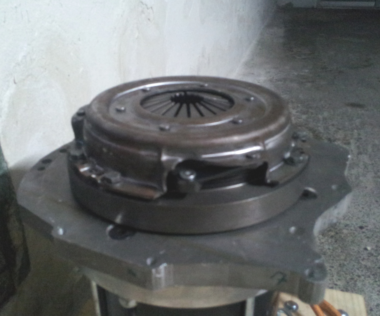
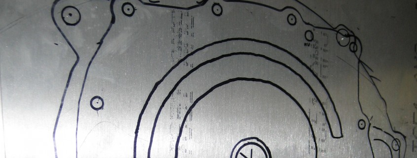
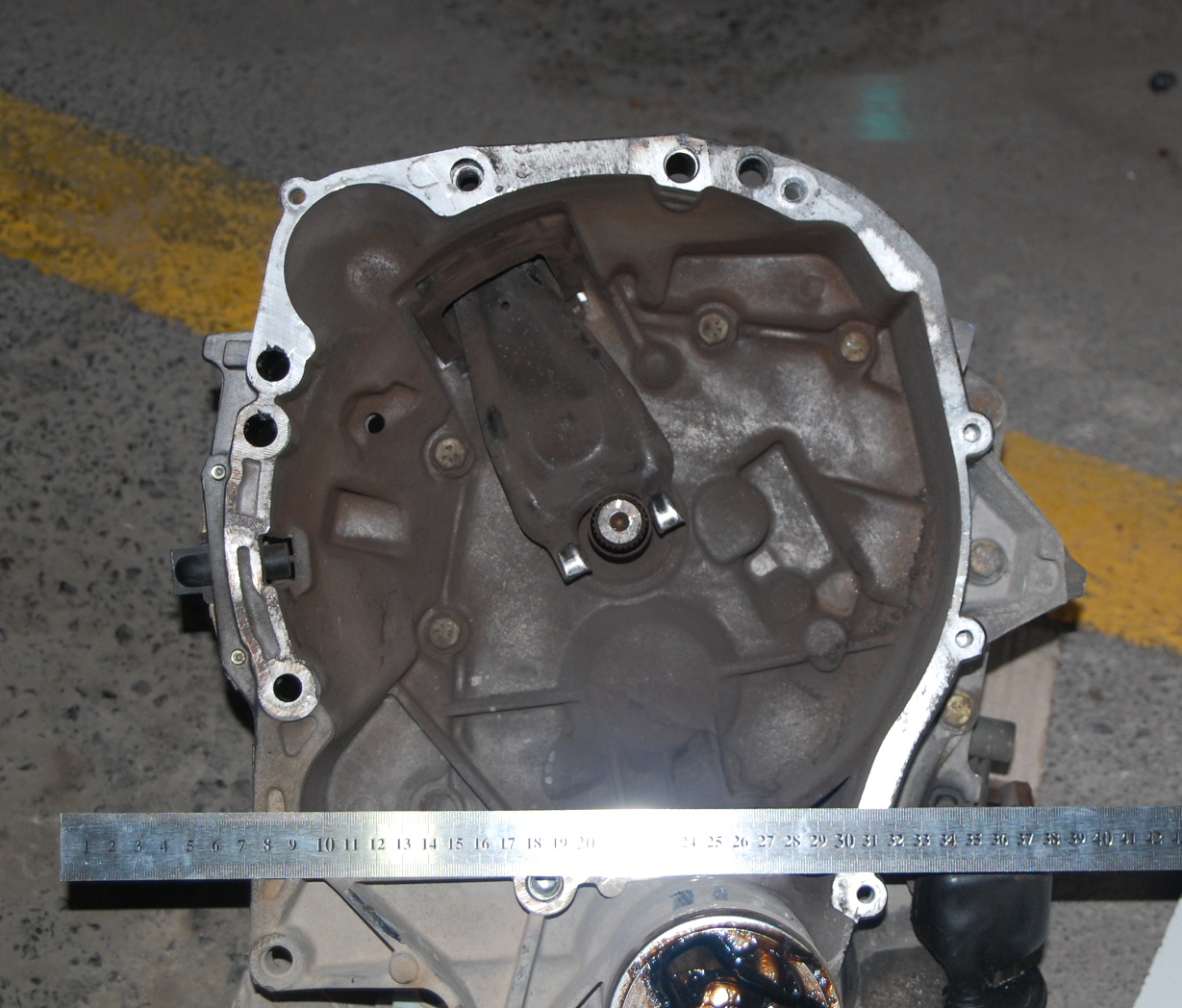
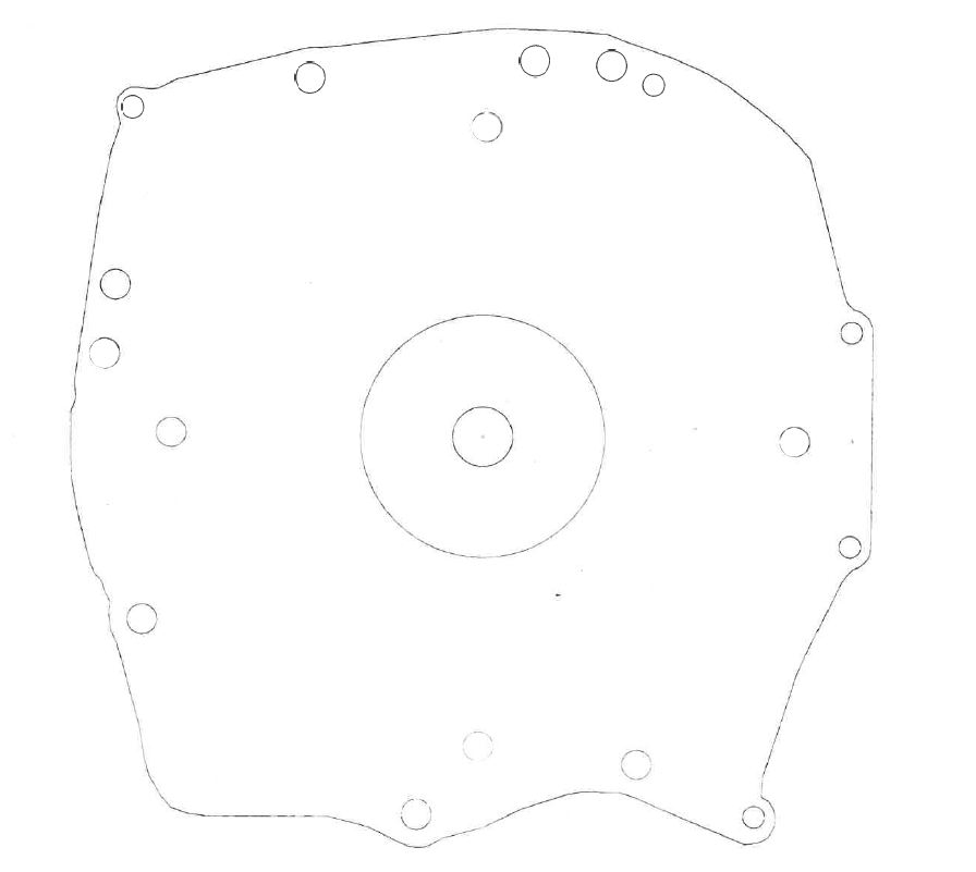
The entire drive assembly is installed on the Mini’s sub-frame, so mechanical installation is a simple step from replacing the old sub-frame with the new one from the kit. Something that the car workshops will appreciate because of how easy and fast this operation is.

How will the kit approval process be?

Well, as simple as there is nothing to do. The kit will be distributed with the approved conformity reports (including the batteries approved with the R100V2), which will suffice with the workshop certificate that assembles it to go to the Technical inspection service (MOT in the UK) and update the Mini’s technical sheet.

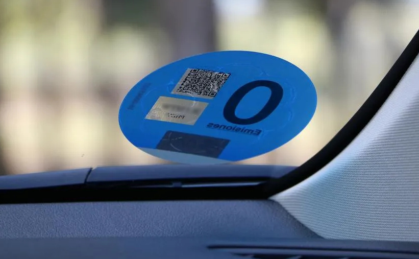
The Mini will be a similar vehicle, weighing exactly the same (about 650 kg), with its four seats and running on electricity, it will be possible to obtain the ZERO label without any difficulty. Of course, a silent, more fluid drive, with regenerative braking and ready to continue being driven for many more years.

Coupling, make it right the third time.

This is one of the most, if not the most important and tricky mechanical manipulations you have to do when converting a vehicle into electric. Connecting the electric motor to the existing transmission is a big debate, as you can just connect both axis together with some sort a coupler or do it using a clutch.


50_coupling

Usually, both axis have different diameter, splines or are in C-fase (as they say in America), so you will need two different couplers, one for each shaft (motor and gear-box).


51_coupling

Now, those two couplers can be connected directly or with the original clutch (there is a big debate around this subject). In our case, we will follow the clutch design. The main reason is efficiency, as having the ability of changing gears, will give you more efficiency in all cases of the driving, such short, medium and long gears. Although this approach is a bit more complicated in implementing, as the flywheel needs to be adapted to the motor shaft, the driving of the car will be as similar as with the combustion engine.

The first part of this transformation is to have the adapter plate mounted in the motor so the flywheel attached keeps in the same position in relation to the gearbox.

52b_coupling


52_coupling


Then, we need to attach the flywheel to the motor with an adapter. You can use a steel coupler from Lovejoy or Rotex, machined exactly for the electric motor shaft. It is also very important to measure all the components including the clutch that will go inside the gearbox, so they all fit perfectly.

Once the flywheel machined and attached to the motor, it is time to screw the clutch to the flywheel. From that point on, the operation it is just a standard clutch installation.


53_coupling


54_coupling
Now, in the 1st attempt to install the clutch, it all went smooth a part from a little periodic noise from inside the gearbox. So, we had to dismantle the clutch again to see what happened. Our surprise was that the flywheel was touching very lightly inside the gearbox. That was the 1st problem easily solved by reducing the flywheel or by carving a bit the specific gearbox area where the flywheel was touching.


55_coupling

Another and second problem was the flywheel, even that was correctly inserted into the splined motor shaft; it wasn’t properly screwed, so that centrifuge force could cause the flywheel to move forwards touching the gearbox shaft. So apart from soldering a coupler in the centre of the flywheel, we asked for a whole too to be able to screw and stop the flywheel.
Now this modification caused to move the block flywheel-clutch forwards 6 mm, so we had to cut the gearbox shaft 7 mm.


58_coupling

Also we discovered that the flywheel wasn’t properly turning flat respect the axis, so we sent it to a machinist to rectify that tiny difference and also to reduce the diameter of the flywheel, with that we solve 2 issues. Removing mass of it, so it would had less inertia and also avoid touching the gearbox inside.


56_coupling

The final result was this 3rd attempt, where the flywheel was turning flat against the clutch disk, was fitted to the motor shaft, the diameter was much smaller, so it wouldn’t touch inside the gearbox and had less mass, so less inertia and better performance. It needed to be balanced (to have the same mass radially so it wouldn’t vibrate at high rpm) , but as the flywheel was already balanced when manufactured, we trust it would still be balanced after the rectification. The gearbox shaft was also cut 7 mm to receive the motor block. And once all modified it all fitted as a glove.


57_coupling


The final result fitted quite well. Tested at high rpm and ahd no vibrations at all.


59_coupling

The adapter plate

One of the key aspects of a conversion is how to connect the existing gearbox to the new electric motor. This is normally done by an adapter plate that fits in both sides, the old gear box and the new motor.

This has to be designed and fabricated with high precision, as the geometry of the whole transmission is under jeopardy if there are errors. There are already manufacturers with already made adapter plates designed and proven to be working perfect. The other option, will cost more time, but it may be cheaper, is to design yourself. That was my case, as so far none did a conversion for a Renault Twingo yet.

So, I decided to design it myself, and give the machinist an sketch of the actual plate.

The plate needs to be made out of a material that needs to be strong, light and cheap. The perfect balance between those 3 variables is aluminium, that is why 99% of the adapter plates are done in such material.

The thickness for the adapter plate depends on the torque and power for the electric motor. For a 14 Kw motor I was recommended a 17mm plate, but my local supplier only had 10mm or 20mm (a paradox working next to Alcoa), so I went for 20mm, that would not add much more weight and it would improve how strong the joint would be.

I started to disassemble the gearbox, and making a template based on a front picture.

20_adapter_plate

After having a proper front picture, I edited with a photo manipulation software (The Gimp) to have just the shape of it.

21_adapter_plate

Once I have a shape of it, I started taking measurements from the centre to the screw holes, between them, and so on, to have a real measurements of it. As in this procedure, error needs to be near zero, I recommend to use a good calibre.

22_adapter_plate

Once all measure have been done (double check and triple check), I draw that template into a 2D CAD software (LibreCAD), and draw many references within the same distances, all the centre points of the pin holes and the actual centre.

23_adapter_plate

Then, when I finished drawing all the circles and, I measured within the 2D CAD software all lines and compare with the real measurements. Surprise, surprise..I had some minor errors.

24_adapter_plate
After double checking the real measurements and the positions in the 2D draw, I printed out in paper 100% sized, and I could see all the wholes were in the exact position, so I gave the design pre- green light.

I took the final design to the machinist as ask him to fabricate a 1mm cheap copy just to try all the screws. They have a super-sized kind of plotter/cutter that can cut  2 cms aluminium as it was butter.

25_adapter_plate

I tried the 1mm template and I fitted like a glove. Just one small 8mm was a bit miss-aligned (about 0.5 mm), the rest all fitted perfect. So I gave the 100% green light and I asked the machinist to cut it in a 20 mm aluminium plate. Even though it took some time as the were out of stock, finally I had it and connect both, gearbox and motor like a charm.

26_adapter_plate