Testing, testing, .. out road.

60_testing
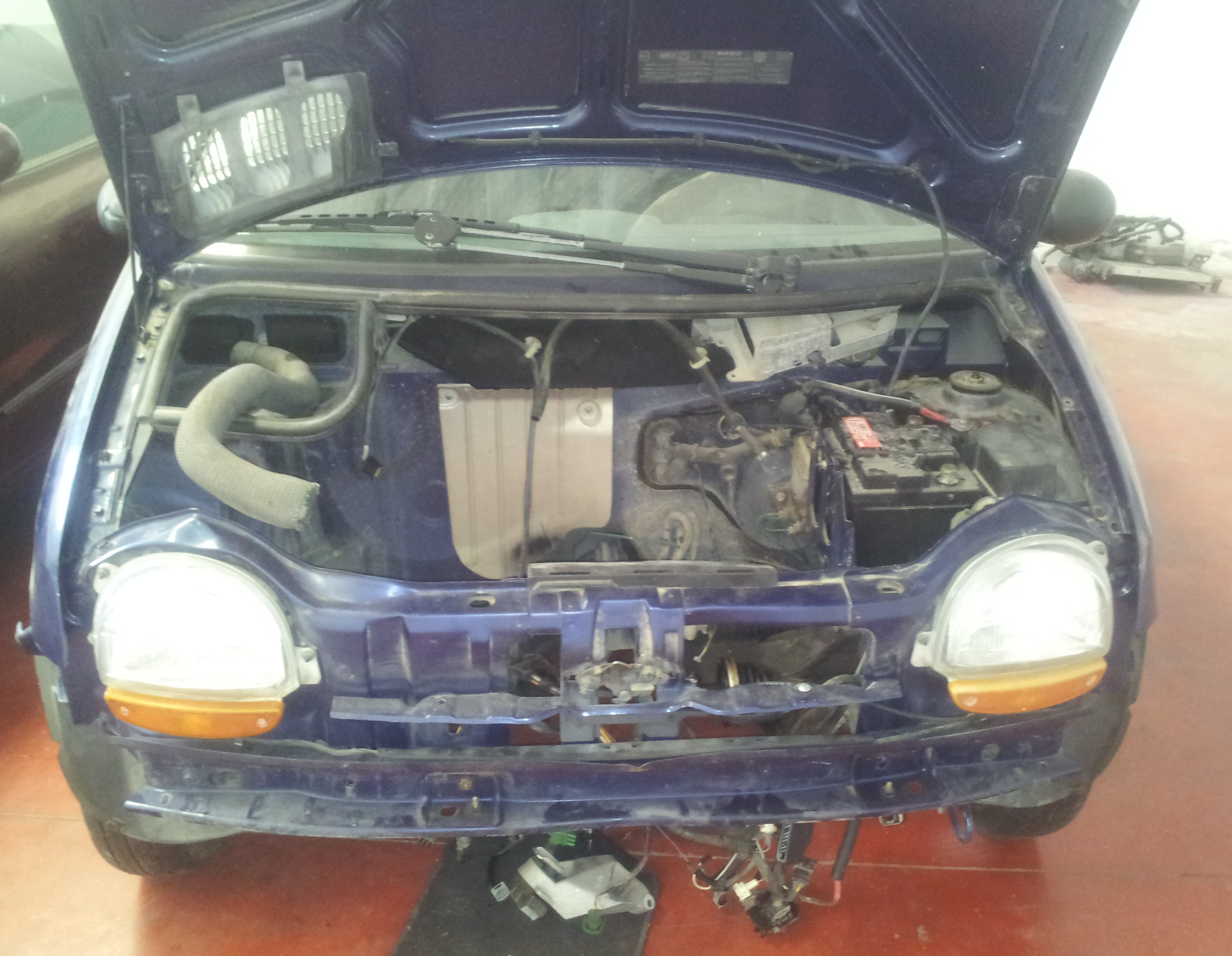
The conversion of a petrol or diesel vehicle is the most sustainable and economical way of driving a perfect electric car. The main idea behind this, is to re-use all the vehicle´s components that have no impact in the internal combustion engine, and to substitute it with a full electric motor. Engine, radiator, petrol tank, exhaust tubes, alternator, etc will be removed, reducing the car´s weight. By having a chassis with all the necessary parts for driving, as interior, brakes, tyres, shock absorbers, etc, all effort is reduced to install and design an electric system with a motor and batteries.

61_testing
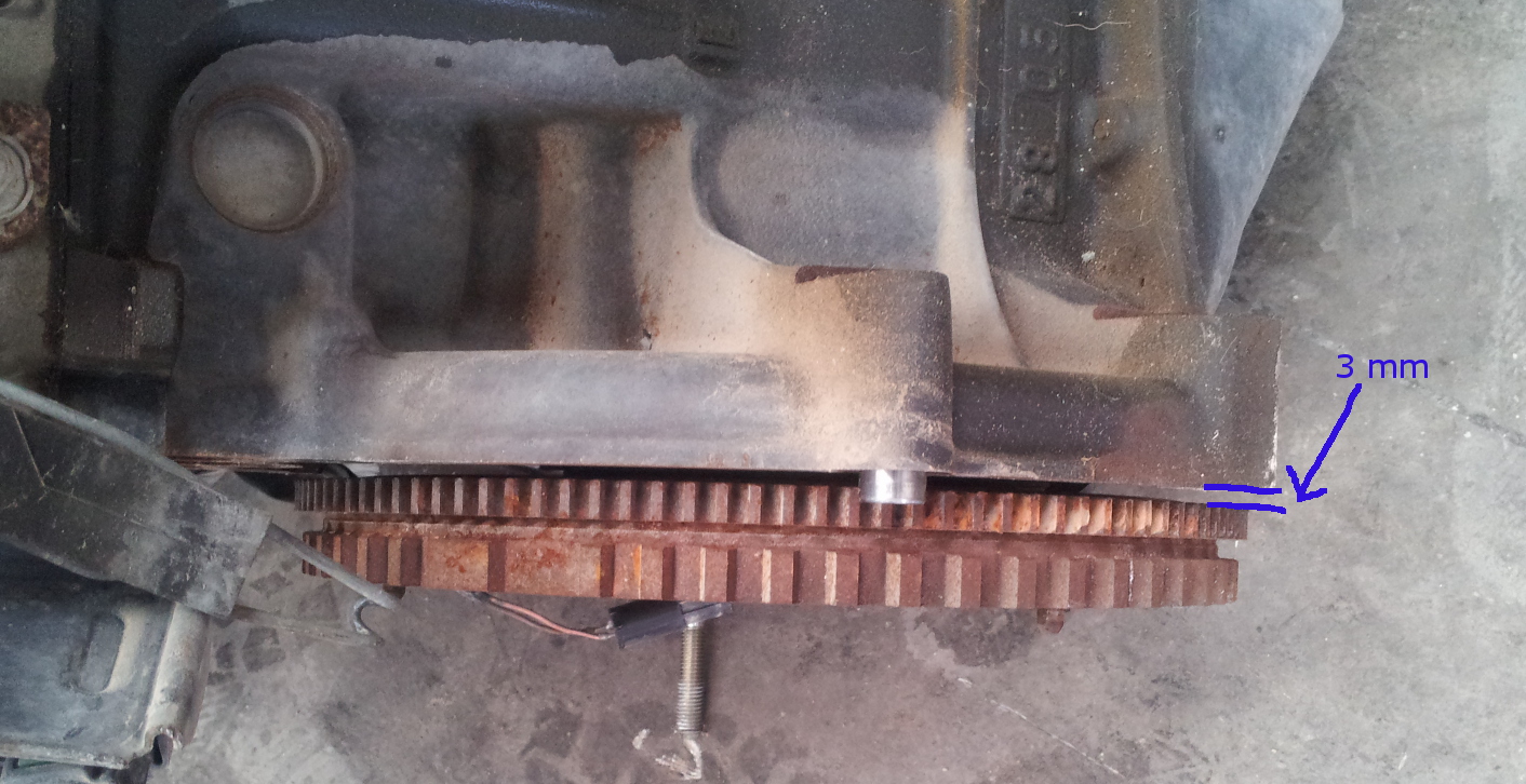
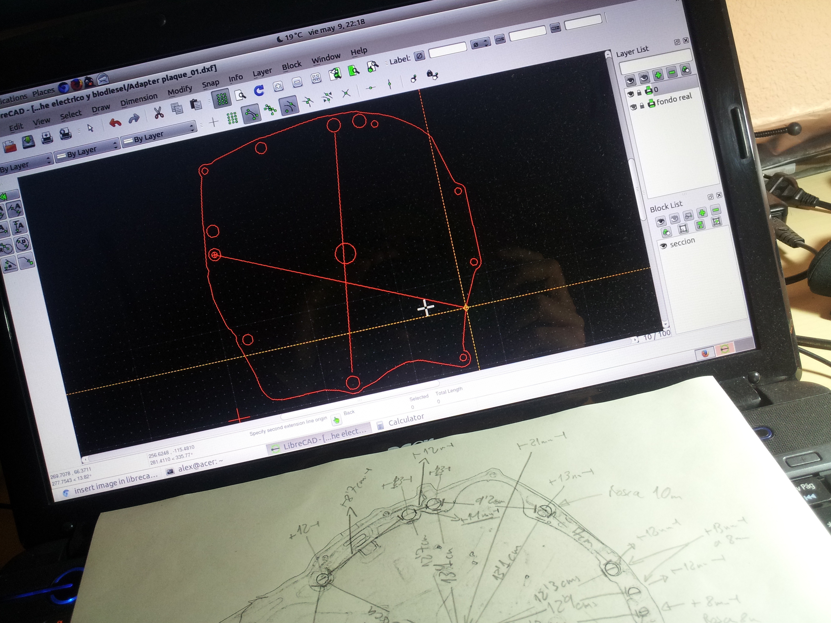
It is very important to choose a good design for the electric system, electric motor, battery pack and motor controller should have the same specifications in power and speed to the ones the car when it was originally designed. Too much power could damage the traction components or may not respond as well to breaking, and too little could cause the gears no to acquire the adequate speed.

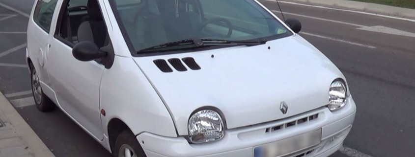
Elektrun is a project that was born two years ago to probe the concept of transforming a city car to electric, ideal for short trips within the city.  We have chosen a Renault Twingo to build a prototype,  it is a vehicle with little weight and a reduced size, and after two years of design, test and experiments we have made it work.

62_testing
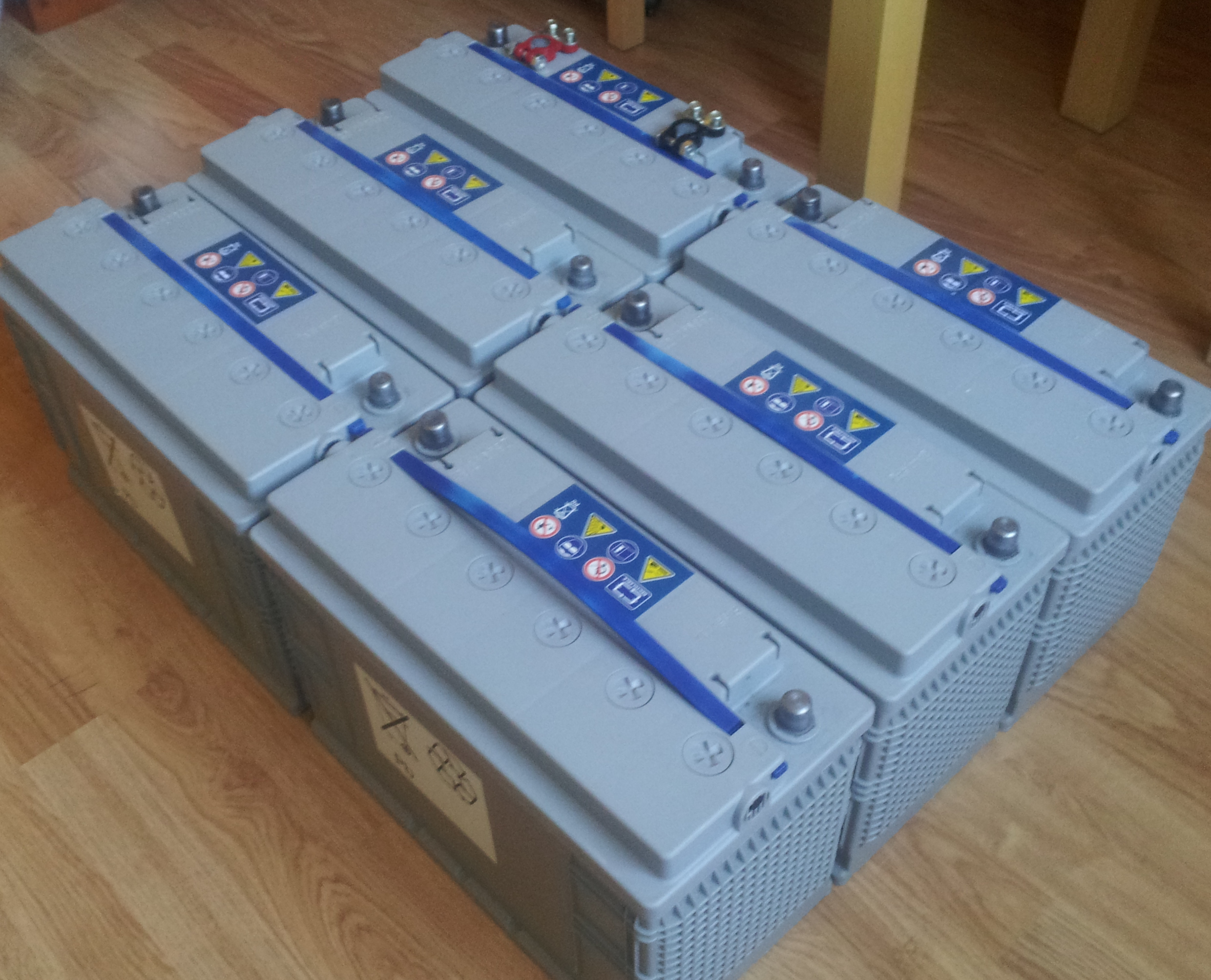
The main issue for this kind of transformation is the range the batteries will achieve. Now days there are cars that can drive 700kms in one single charge, in order to achieve that, it needs at least between 70Kw and 80Kw. Our prototype comes with a 7,4Kw.


63_testing
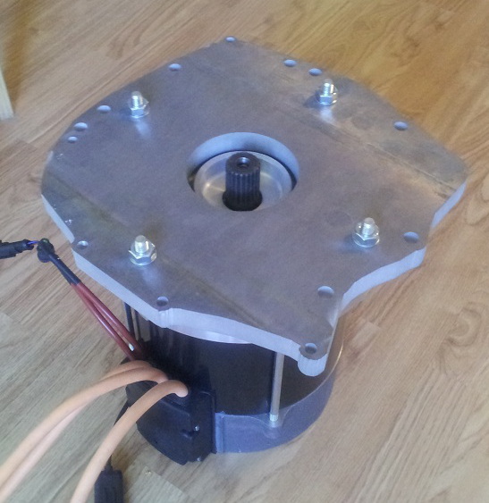
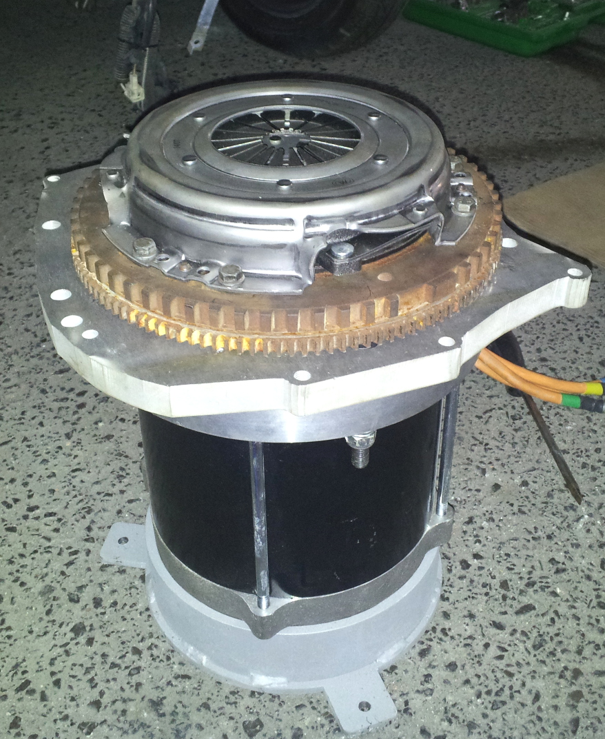
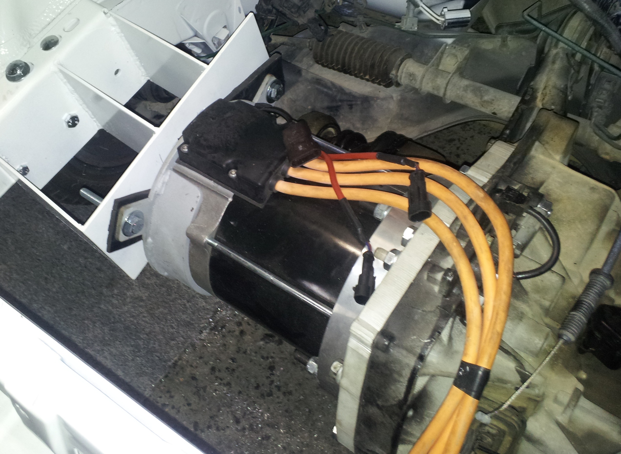
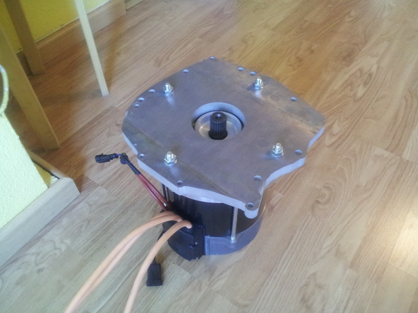
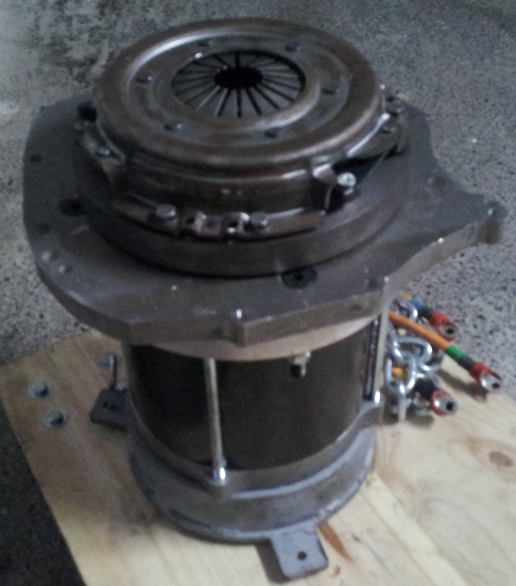
This prototype has an 15KW AC induction motor with a maximum torque of 80Nm, a battery pack of 72V and 100Ah, it has an 80V and 350Amp controller. This can speed the car to 90km/h in 5th gear.

The first tests shown the total weight didn’t affect at all in corners, the shock absorbers responded well as expected, and by removing the engine noise the driving was much more comfortable.

64_testing
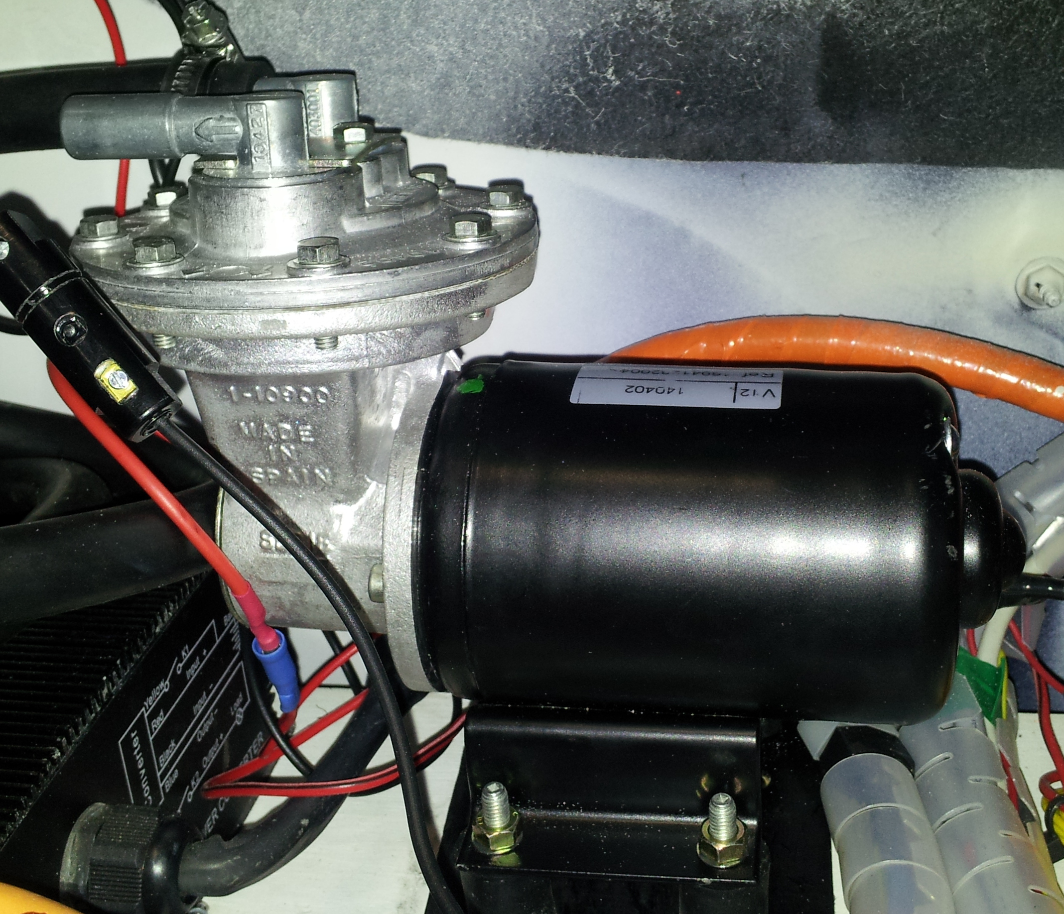
An additional vacuum pump was installed to help the braking system. The braking was also performing very well as, it responded to hard braking and kept the car stopped in steep ramps.


65_testing
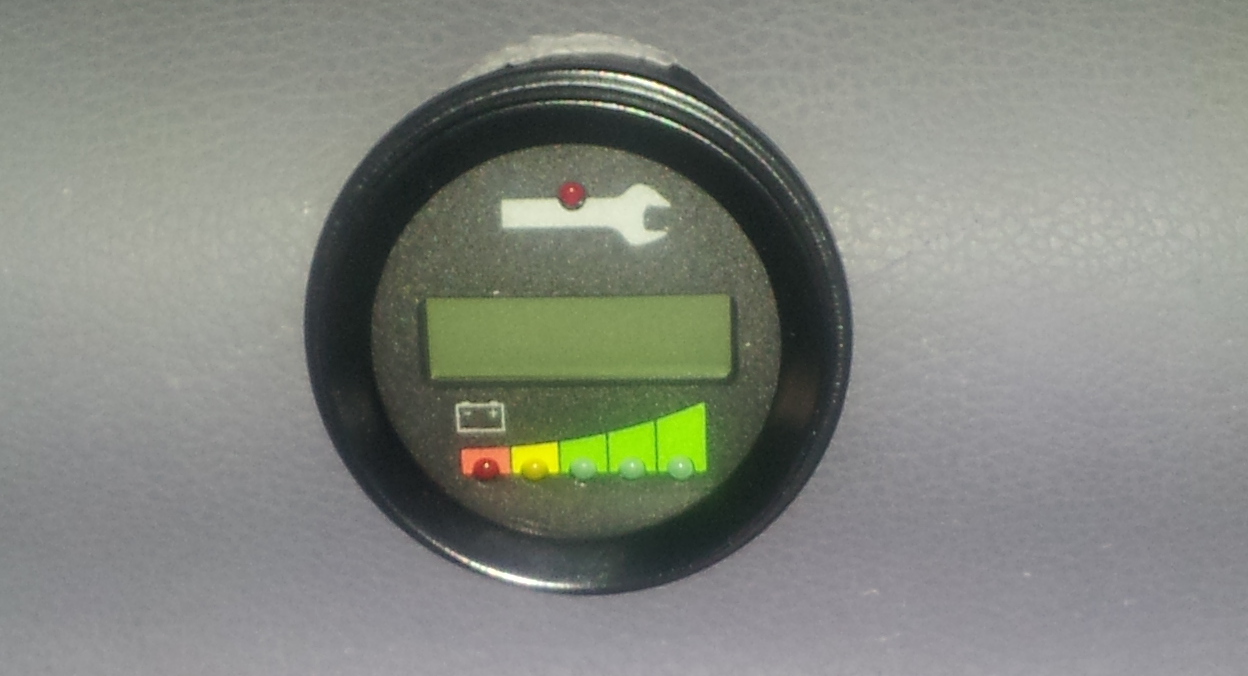
A small display was installed in the interior to monitor, at any time, battery usage, current, motor temperature, state of charge, etc.


66_testingLights and interior accessories as electric windows, radio, air flow, window cleaner, etc were kept in the car.

This car takes 8 hours to fully charge the battery pack, although there are chargers that could reduce this time from 6 to 4 hours.


You can see a video about the first tests here:

Coupling, make it right the third time.

This is one of the most, if not the most important and tricky mechanical manipulations you have to do when converting a vehicle into electric. Connecting the electric motor to the existing transmission is a big debate, as you can just connect both axis together with some sort a coupler or do it using a clutch.


50_coupling

Usually, both axis have different diameter, splines or are in C-fase (as they say in America), so you will need two different couplers, one for each shaft (motor and gear-box).


51_coupling

Now, those two couplers can be connected directly or with the original clutch (there is a big debate around this subject). In our case, we will follow the clutch design. The main reason is efficiency, as having the ability of changing gears, will give you more efficiency in all cases of the driving, such short, medium and long gears. Although this approach is a bit more complicated in implementing, as the flywheel needs to be adapted to the motor shaft, the driving of the car will be as similar as with the combustion engine.

The first part of this transformation is to have the adapter plate mounted in the motor so the flywheel attached keeps in the same position in relation to the gearbox.

52b_coupling


52_coupling


Then, we need to attach the flywheel to the motor with an adapter. You can use a steel coupler from Lovejoy or Rotex, machined exactly for the electric motor shaft. It is also very important to measure all the components including the clutch that will go inside the gearbox, so they all fit perfectly.

Once the flywheel machined and attached to the motor, it is time to screw the clutch to the flywheel. From that point on, the operation it is just a standard clutch installation.


53_coupling


54_coupling
Now, in the 1st attempt to install the clutch, it all went smooth a part from a little periodic noise from inside the gearbox. So, we had to dismantle the clutch again to see what happened. Our surprise was that the flywheel was touching very lightly inside the gearbox. That was the 1st problem easily solved by reducing the flywheel or by carving a bit the specific gearbox area where the flywheel was touching.


55_coupling

Another and second problem was the flywheel, even that was correctly inserted into the splined motor shaft; it wasn’t properly screwed, so that centrifuge force could cause the flywheel to move forwards touching the gearbox shaft. So apart from soldering a coupler in the centre of the flywheel, we asked for a whole too to be able to screw and stop the flywheel.
Now this modification caused to move the block flywheel-clutch forwards 6 mm, so we had to cut the gearbox shaft 7 mm.


58_coupling

Also we discovered that the flywheel wasn’t properly turning flat respect the axis, so we sent it to a machinist to rectify that tiny difference and also to reduce the diameter of the flywheel, with that we solve 2 issues. Removing mass of it, so it would had less inertia and also avoid touching the gearbox inside.


56_coupling

The final result was this 3rd attempt, where the flywheel was turning flat against the clutch disk, was fitted to the motor shaft, the diameter was much smaller, so it wouldn’t touch inside the gearbox and had less mass, so less inertia and better performance. It needed to be balanced (to have the same mass radially so it wouldn’t vibrate at high rpm) , but as the flywheel was already balanced when manufactured, we trust it would still be balanced after the rectification. The gearbox shaft was also cut 7 mm to receive the motor block. And once all modified it all fitted as a glove.


57_coupling


The final result fitted quite well. Tested at high rpm and ahd no vibrations at all.


59_coupling

The adapter plate

One of the key aspects of a conversion is how to connect the existing gearbox to the new electric motor. This is normally done by an adapter plate that fits in both sides, the old gear box and the new motor.

This has to be designed and fabricated with high precision, as the geometry of the whole transmission is under jeopardy if there are errors. There are already manufacturers with already made adapter plates designed and proven to be working perfect. The other option, will cost more time, but it may be cheaper, is to design yourself. That was my case, as so far none did a conversion for a Renault Twingo yet.

So, I decided to design it myself, and give the machinist an sketch of the actual plate.

The plate needs to be made out of a material that needs to be strong, light and cheap. The perfect balance between those 3 variables is aluminium, that is why 99% of the adapter plates are done in such material.

The thickness for the adapter plate depends on the torque and power for the electric motor. For a 14 Kw motor I was recommended a 17mm plate, but my local supplier only had 10mm or 20mm (a paradox working next to Alcoa), so I went for 20mm, that would not add much more weight and it would improve how strong the joint would be.

I started to disassemble the gearbox, and making a template based on a front picture.

20_adapter_plate

After having a proper front picture, I edited with a photo manipulation software (The Gimp) to have just the shape of it.

21_adapter_plate

Once I have a shape of it, I started taking measurements from the centre to the screw holes, between them, and so on, to have a real measurements of it. As in this procedure, error needs to be near zero, I recommend to use a good calibre.

22_adapter_plate

Once all measure have been done (double check and triple check), I draw that template into a 2D CAD software (LibreCAD), and draw many references within the same distances, all the centre points of the pin holes and the actual centre.

23_adapter_plate

Then, when I finished drawing all the circles and, I measured within the 2D CAD software all lines and compare with the real measurements. Surprise, surprise..I had some minor errors.

24_adapter_plate
After double checking the real measurements and the positions in the 2D draw, I printed out in paper 100% sized, and I could see all the wholes were in the exact position, so I gave the design pre- green light.

I took the final design to the machinist as ask him to fabricate a 1mm cheap copy just to try all the screws. They have a super-sized kind of plotter/cutter that can cut  2 cms aluminium as it was butter.

25_adapter_plate

I tried the 1mm template and I fitted like a glove. Just one small 8mm was a bit miss-aligned (about 0.5 mm), the rest all fitted perfect. So I gave the 100% green light and I asked the machinist to cut it in a 20 mm aluminium plate. Even though it took some time as the were out of stock, finally I had it and connect both, gearbox and motor like a charm.

26_adapter_plate