The adapter plate
One of the key aspects of a conversion is how to connect the existing gearbox to the new electric motor. This is normally done by an adapter plate that fits in both sides, the old gear box and the new motor.
This has to be designed and fabricated with high precision, as the geometry of the whole transmission is under jeopardy if there are errors. There are already manufacturers with already made adapter plates designed and proven to be working perfect. The other option, will cost more time, but it may be cheaper, is to design yourself. That was my case, as so far none did a conversion for a Renault Twingo yet.
So, I decided to design it myself, and give the machinist an sketch of the actual plate.
The plate needs to be made out of a material that needs to be strong, light and cheap. The perfect balance between those 3 variables is aluminium, that is why 99% of the adapter plates are done in such material.
The thickness for the adapter plate depends on the torque and power for the electric motor. For a 14 Kw motor I was recommended a 17mm plate, but my local supplier only had 10mm or 20mm (a paradox working next to Alcoa), so I went for 20mm, that would not add much more weight and it would improve how strong the joint would be.
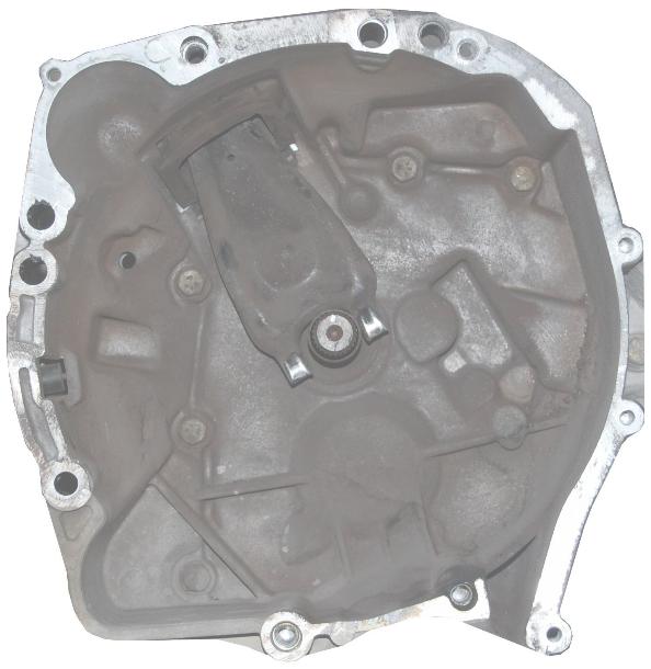
I started to disassemble the gearbox, and making a template based on a front picture.
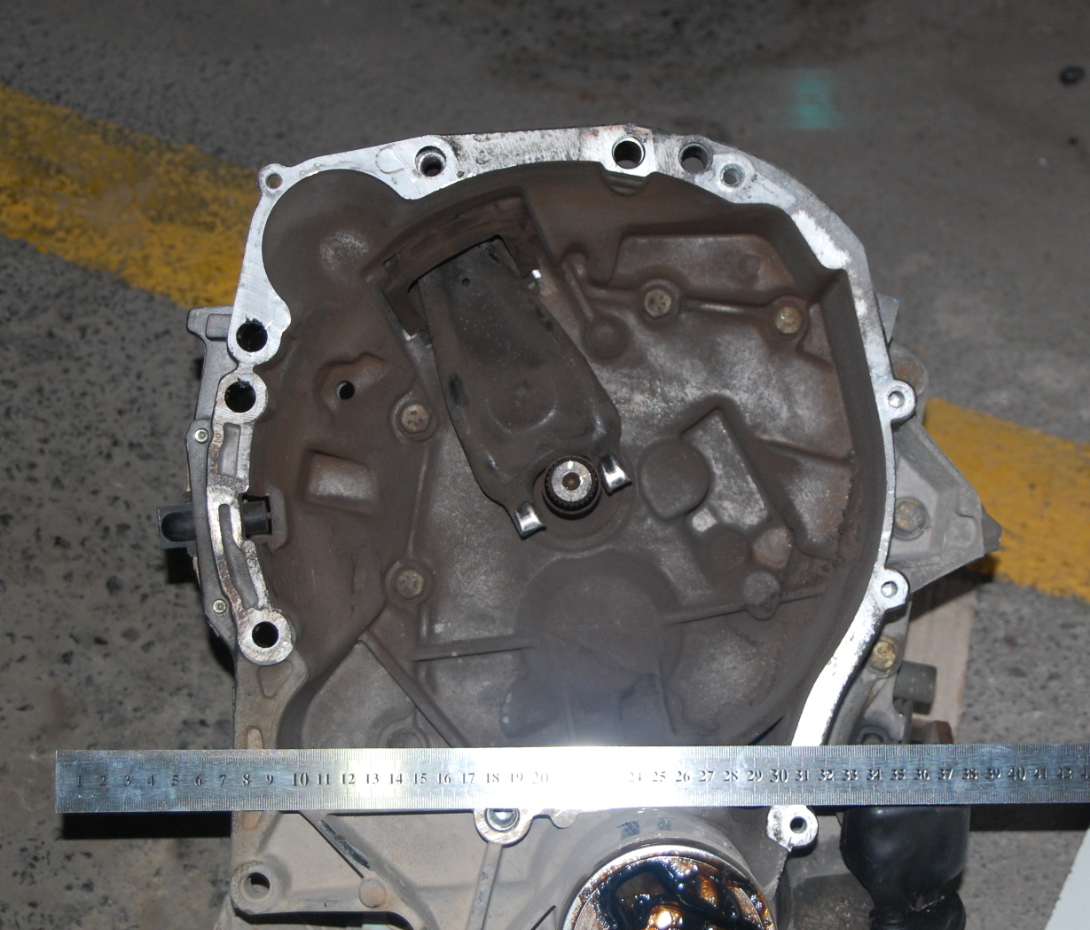
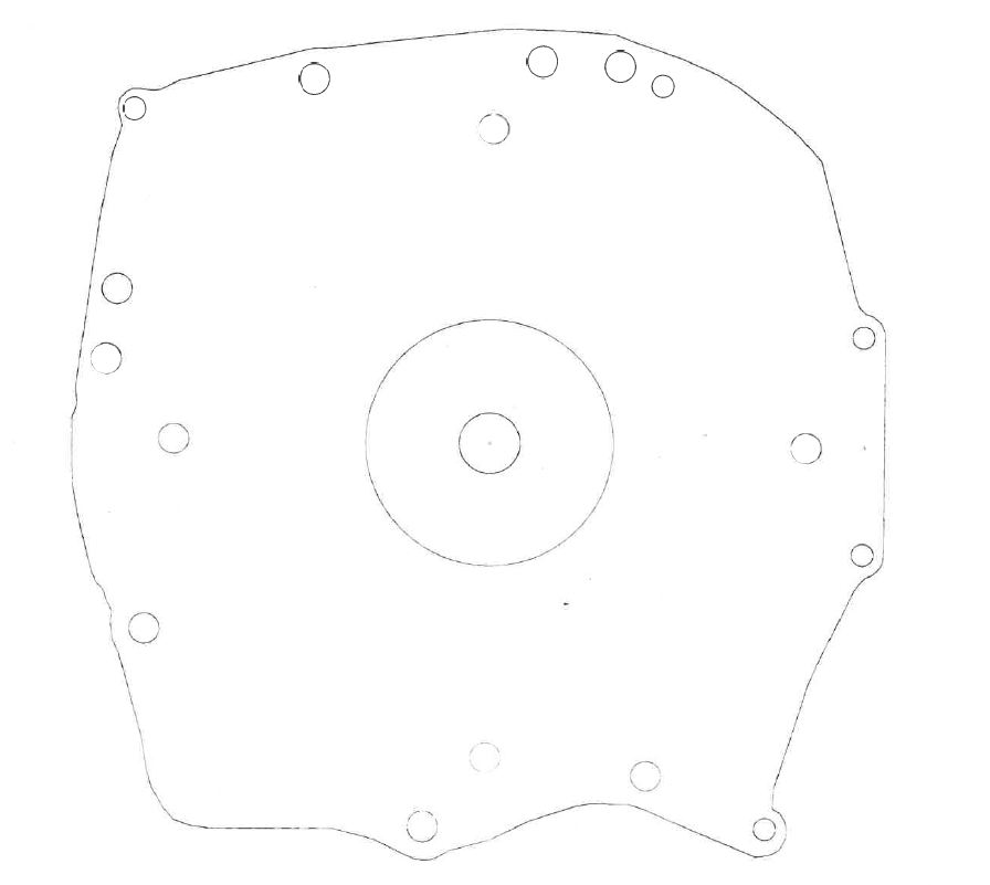
After having a proper front picture, I edited with a photo manipulation software (The Gimp) to have just the shape of it.
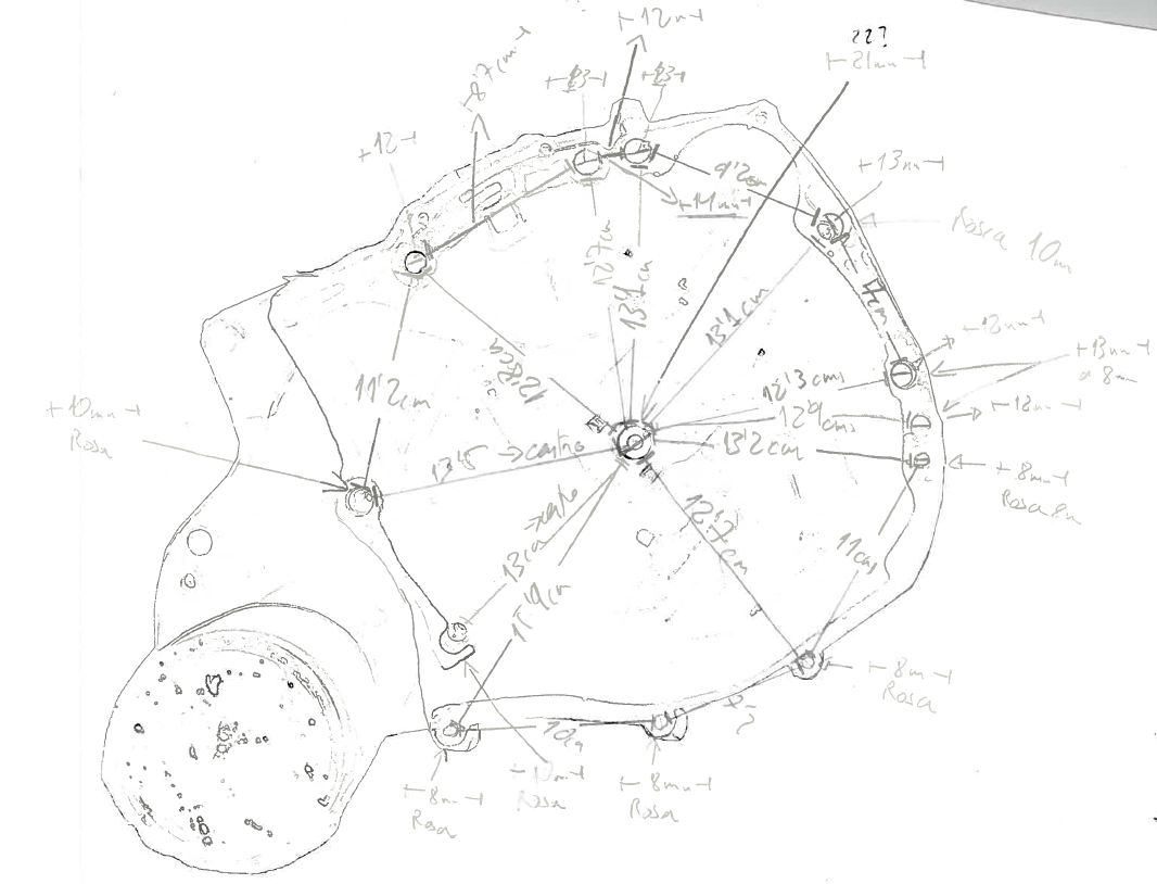
Once I have a shape of it, I started taking measurements from the centre to the screw holes, between them, and so on, to have a real measurements of it. As in this procedure, error needs to be near zero, I recommend to use a good calibre.
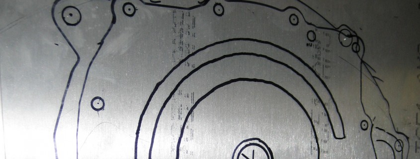
Once all measure have been done (double check and triple check), I draw that template into a 2D CAD software (LibreCAD), and draw many references within the same distances, all the centre points of the pin holes and the actual centre.
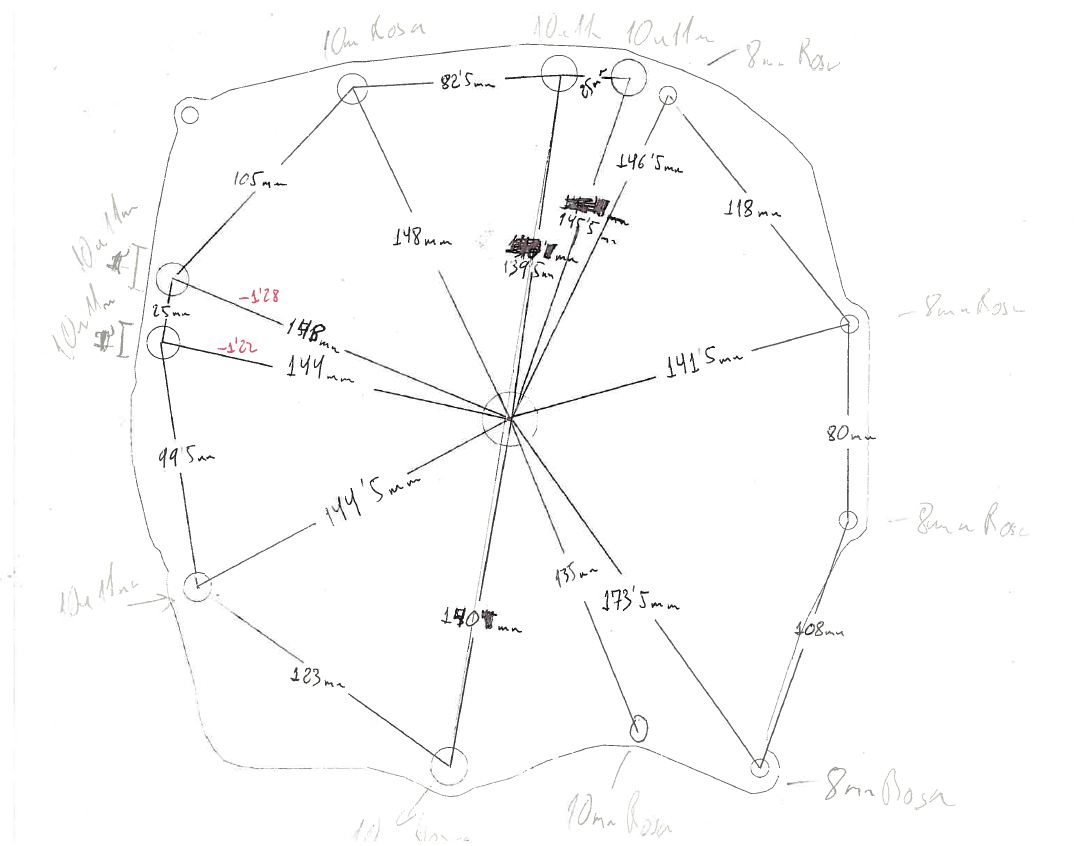
Then, when I finished drawing all the circles and, I measured within the 2D CAD software all lines and compare with the real measurements. Surprise, surprise..I had some minor errors.
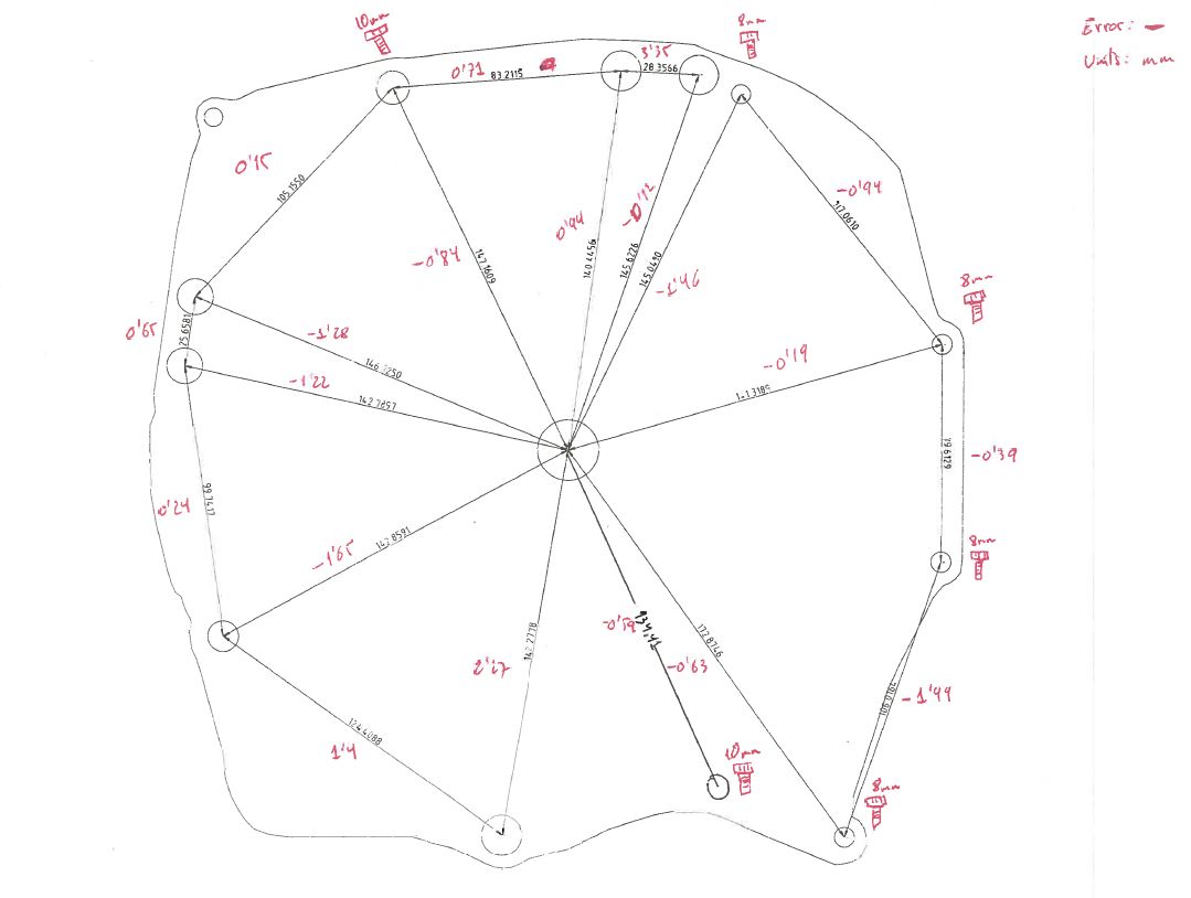
After double checking the real measurements and the positions in the 2D draw, I printed out in paper 100% sized, and I could see all the wholes were in the exact position, so I gave the design pre- green light.
I took the final design to the machinist as ask him to fabricate a 1mm cheap copy just to try all the screws. They have a super-sized kind of plotter/cutter that can cut 2 cms aluminium as it was butter.
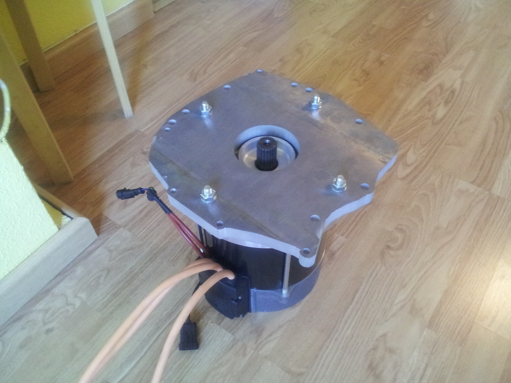
I tried the 1mm template and I fitted like a glove. Just one small 8mm was a bit miss-aligned (about 0.5 mm), the rest all fitted perfect. So I gave the 100% green light and I asked the machinist to cut it in a 20 mm aluminium plate. Even though it took some time as the were out of stock, finally I had it and connect both, gearbox and motor like a charm.