Coupling, make it right the third time.
This is one of the most, if not the most important and tricky mechanical manipulations you have to do when converting a vehicle into electric. Connecting the electric motor to the existing transmission is a big debate, as you can just connect both axis together with some sort a coupler or do it using a clutch.
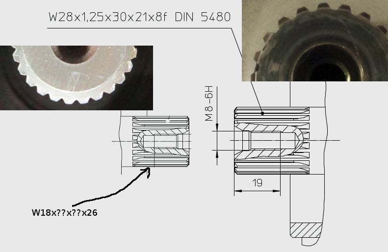
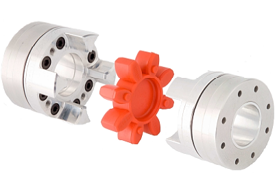
Usually, both axis have different diameter, splines or are in C-fase (as they say in America), so you will need two different couplers, one for each shaft (motor and gear-box).
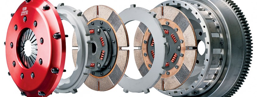
Now, those two couplers can be connected directly or with the original clutch (there is a big debate around this subject). In our case, we will follow the clutch design. The main reason is efficiency, as having the ability of changing gears, will give you more efficiency in all cases of the driving, such short, medium and long gears. Although this approach is a bit more complicated in implementing, as the flywheel needs to be adapted to the motor shaft, the driving of the car will be as similar as with the combustion engine.
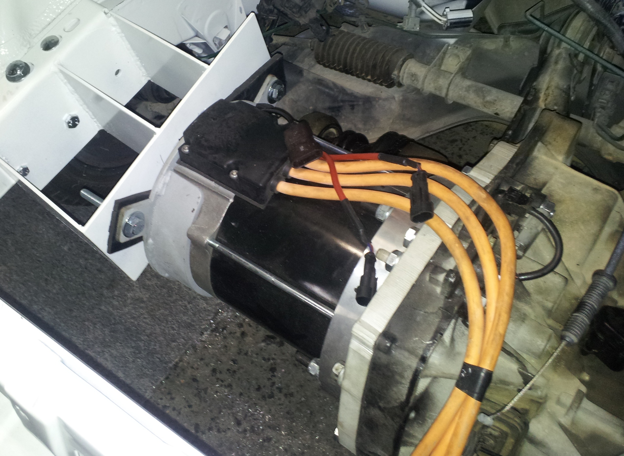
The first part of this transformation is to have the adapter plate mounted in the motor so the flywheel attached keeps in the same position in relation to the gearbox.
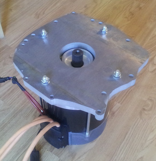
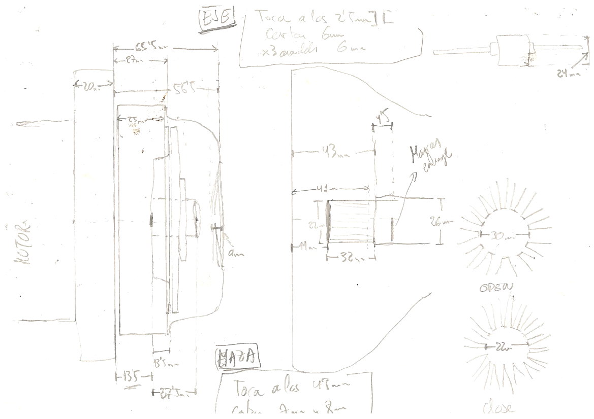
Then, we need to attach the flywheel to the motor with an adapter. You can use a steel coupler from Lovejoy or Rotex, machined exactly for the electric motor shaft. It is also very important to measure all the components including the clutch that will go inside the gearbox, so they all fit perfectly.
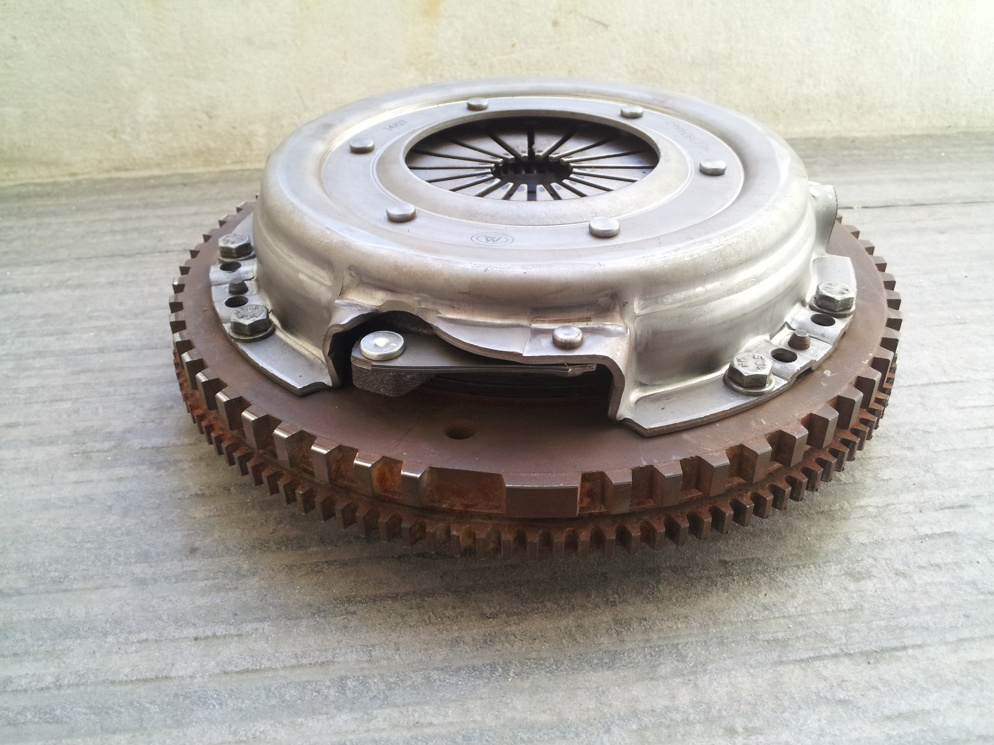
Once the flywheel machined and attached to the motor, it is time to screw the clutch to the flywheel. From that point on, the operation it is just a standard clutch installation.
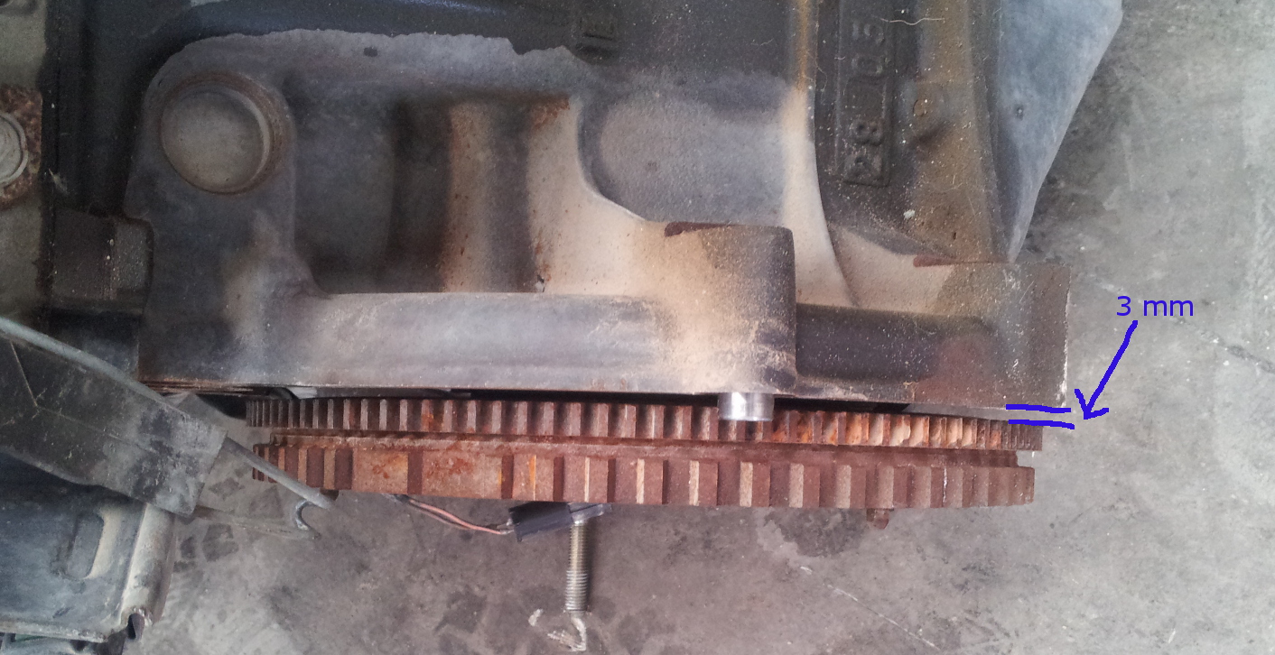
Now, in the 1st attempt to install the clutch, it all went smooth a part from a little periodic noise from inside the gearbox. So, we had to dismantle the clutch again to see what happened. Our surprise was that the flywheel was touching very lightly inside the gearbox. That was the 1st problem easily solved by reducing the flywheel or by carving a bit the specific gearbox area where the flywheel was touching.
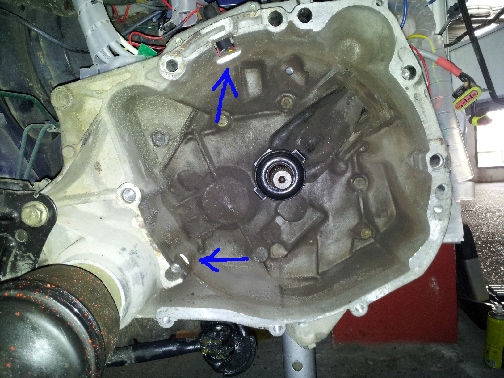
Another and second problem was the flywheel, even that was correctly inserted into the splined motor shaft; it wasn’t properly screwed, so that centrifuge force could cause the flywheel to move forwards touching the gearbox shaft. So apart from soldering a coupler in the centre of the flywheel, we asked for a whole too to be able to screw and stop the flywheel.
Now this modification caused to move the block flywheel-clutch forwards 6 mm, so we had to cut the gearbox shaft 7 mm.
Also we discovered that the flywheel wasn’t properly turning flat respect the axis, so we sent it to a machinist to rectify that tiny difference and also to reduce the diameter of the flywheel, with that we solve 2 issues. Removing mass of it, so it would had less inertia and also avoid touching the gearbox inside.
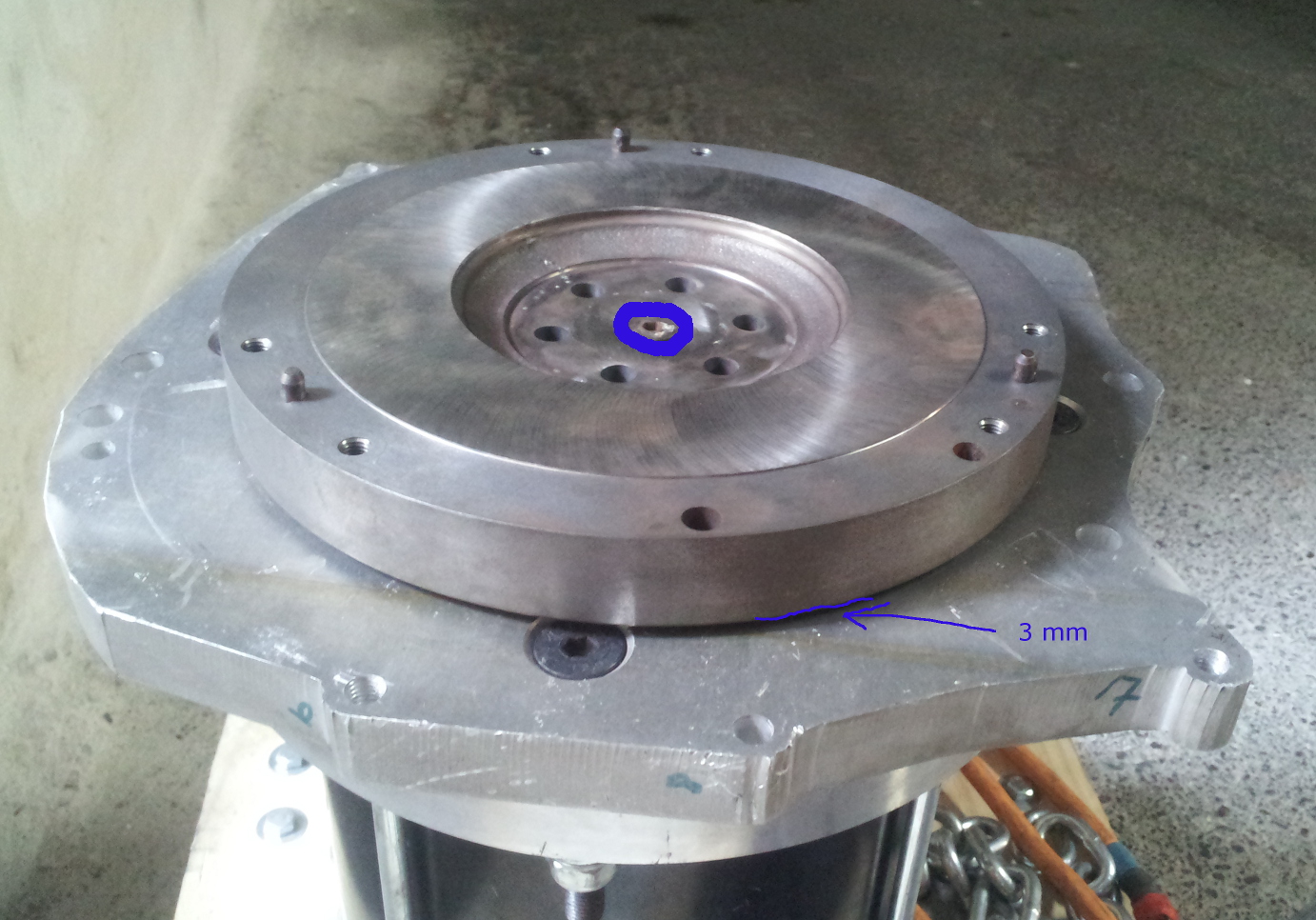
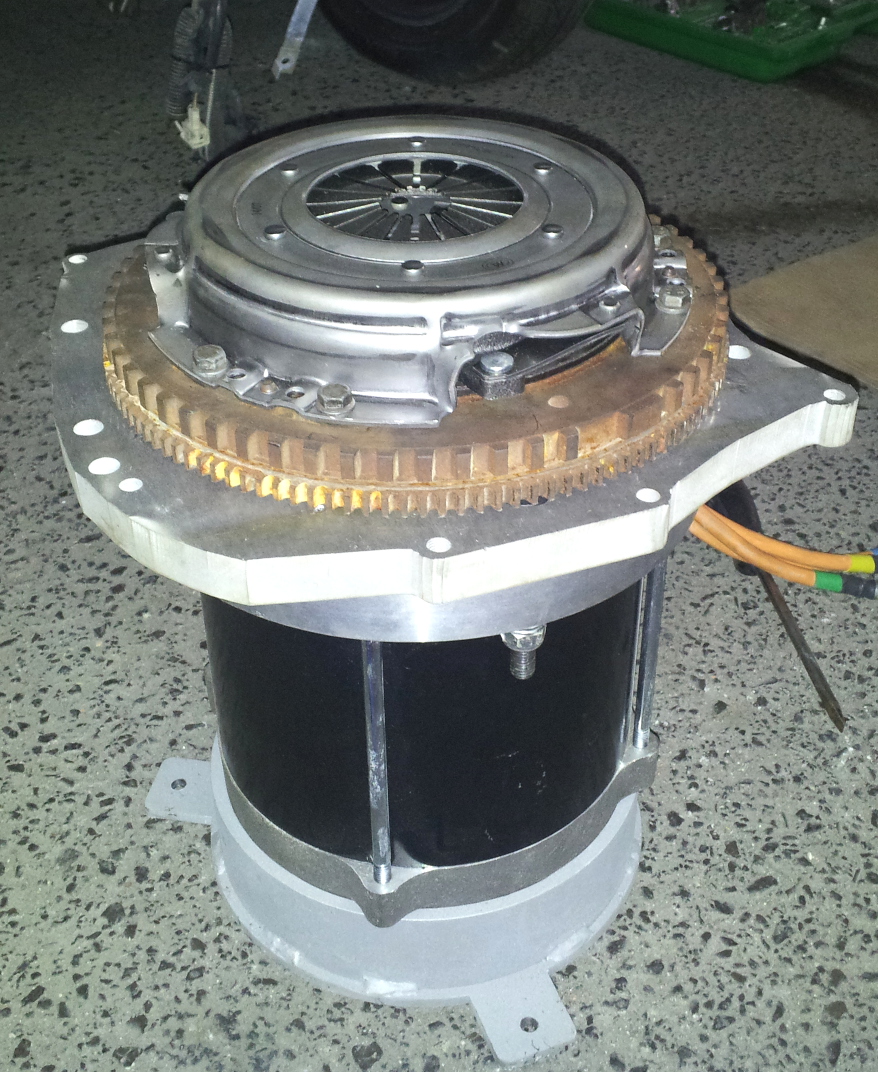
The final result was this 3rd attempt, where the flywheel was turning flat against the clutch disk, was fitted to the motor shaft, the diameter was much smaller, so it wouldn’t touch inside the gearbox and had less mass, so less inertia and better performance. It needed to be balanced (to have the same mass radially so it wouldn’t vibrate at high rpm) , but as the flywheel was already balanced when manufactured, we trust it would still be balanced after the rectification. The gearbox shaft was also cut 7 mm to receive the motor block. And once all modified it all fitted as a glove.
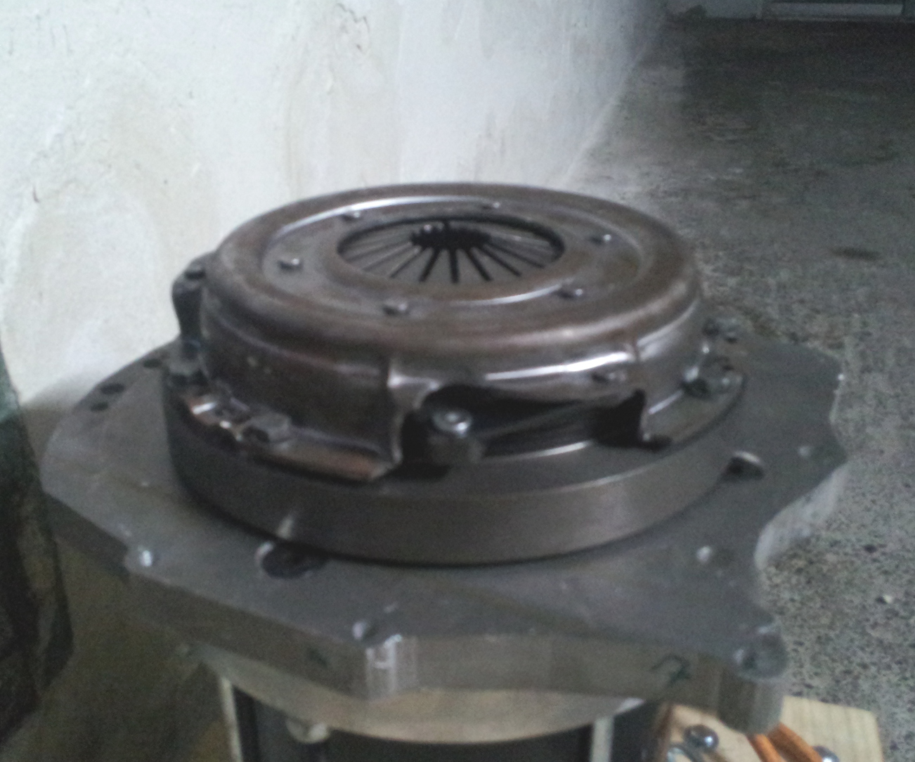
The final result fitted quite well. Tested at high rpm and ahd no vibrations at all.